67 Rag Joint Steering Coupler Operation Question - NCRS Discussion Boards

67 Rag Joint Steering Coupler Operation Question

Collapse
X
 
  • Time
  • Show
Clear All
new posts
  • Al P.
    Expired
    • February 15, 2011
    • 87

    67 Rag Joint Steering Coupler Operation Question

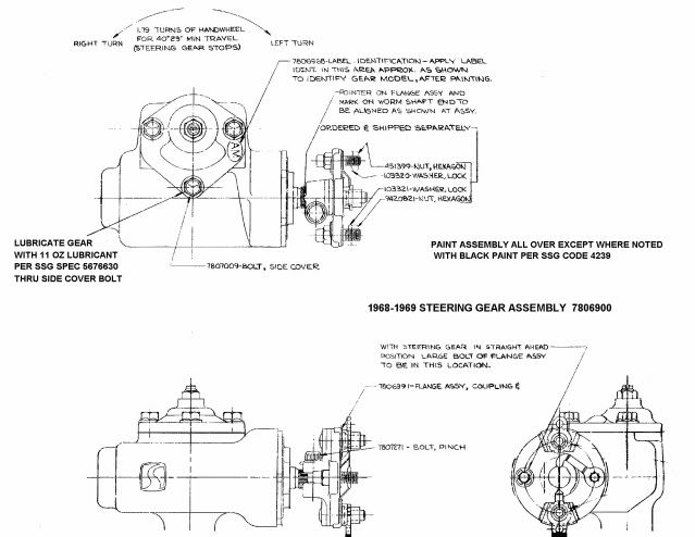
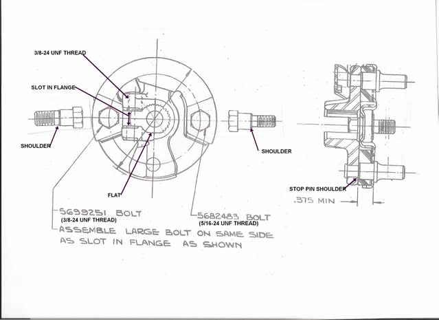
    I often wondered how the steering coupler actually operates when in normal use. Since it looks like 2 sides that are held together with 2 bolts at 9 and 3 o'clock and pins located at 12 and 6 o'clock of the joint with a fabric disc between the 2 part coupler assembly.

    The question for the day is when the car is stationery or being driven and your turn the wheel right or left, does the firewall side (metal flange where "pins" are at 12 and 6 o'clock) actually turn and press against the pins (that are on the steering box side of the coupler) to begin moving the steering box side of the joint to steer the car?

    I keep looking at mine and wonder if this is the way it works as it's design doesn't seem to be a "solid" coupling device. The design looks as if the "Pins" when the steering wheel is positioned (going straight) do not contact the coupler until the steering wheel is either moved left or right to steer the car? So there is a small bit of "play" until the coupler pushes the Pin either right or left.

    Is this correct? This gizmo fascinates me..
  • Jim S.
    Expired
    • August 31, 2001
    • 730

    #2
    Re: 67 Rag Joint Steering Coupler Operation Question

    I assume that you have a 1967 Vette. There were two different coupling discs that were in common use within General Motors cars and trucks. A 7 ply disc, that was a lamination of 7 layers of cotton cloth and neoprene rubber. This disc was used on manual steering GM vehicles and all Corvettes (regardless if power or manual steering). The disc was quite stiff and provided good steering feedback. The other type disc was a lamination of 4 layers of neoprene rubber and cotton cloth. This type disc was used on all vehicles equipped with power steering. This 4 ply disc was "softer" than the 7 ply disc but it also did a better job of isolating steering system hydraulic noises from being transferred up the steering shaft and into the driver compartment.

    If you have an original flexible coupling in your car, there should be a metal strap that encircles the hole in the center of the disc. In this scan of the 1968-69 Corvette steering gear, you can see the strap in the picture in the lower right side of the scan. The strap connects the 3 o'clock bolt to the 6 o'clock stop pin. With the flex coupling connected to the steering column flange, you will not be able to see the strap.


    Now the bad news.
    The flexible coupling was never designed to be taken apart and serviced. From your description, it does sound as if your flex coupling is in good shape. However, I would think that with the stiff 7 ply coupling disc, you really shouldn't feel the stop pins unless you were really putting some effort into the steering wheel.

    If you are going to replace the assembly, I would try and locate an original GM replacement part (one with a 7 ply disc - you can actually count the laminations.) There are offshore manufactured parts and even some late GM authorized parts that were assembled with 4 ply discs instead of 7 ply discs. Also the rebuild kits that can be obtained at most automotive suppliers are very inferior. First, they all come with 4 ply discs and also they have common bolts rather than shoulder bolts to attach to the steering column flange.

    Starting around 1971 the ground wire/strap was replaced with a metal screen that was molded into the face of the coupling disc. This screen was used on 4 ply as well as 7 ply discs. You can actually poke your fingers if you grab a screen ground coupling disc by its edge. You won't find any aftermarket assemblies or kits that provide a grounding means through the coupling assembly (i.e. no screen, no strap, no wire). This could mean that your horn may not operate (although the ground current for the horn may find other less reliable paths through the steering column mounts to ground.)

    One other area that you might investigate. Your 1967 Vette has the steering column that mounts directly to the steering gear through the flexible coupling assembly. It is very important that the steering column be aligned precisely to the steering gear. Note, the gear is hard mounted to the frame so there is no adjustment available at the gear. All of the adjustment has to occur with the column mounting.

    The AIM and the Chevrolet shop manuals have some very specific instructions as to aligning the column to the gear.

    You should be able to inspect your connection and determine if your stop pins are central to the cutouts in the column flange. Then rotate your steering wheel 1/4 turn and determine that your pins are still central. If you always find equal clearances, then you can be fairly sure that the column is aligned to the gear.

    Jim

    Comment

    • Al P.
      Expired
      • February 15, 2011
      • 87

      #3
      Re: 67 Rag Joint Steering Coupler Operation Question

      Thank You Jim for all the help on this - I'll go the column route - doesn't look so bad now that I have the details. The one I have in my Vette is the original and "only lasted" 45 years! LOL!!

      Comment

      Working...
      Searching...Please wait.
      An unexpected error was returned: 'Your submission could not be processed because you have logged in since the previous page was loaded.

      Please push the back button and reload the previous window.'
      An unexpected error was returned: 'Your submission could not be processed because the token has expired.

      Please push the back button and reload the previous window.'
      An internal error has occurred and the module cannot be displayed.
      There are no results that meet this criteria.
      Search Result for "|||"