K66 Transistor Ignition - Delco Circuit Module Failure, Diagnosis and Repair - NCRS Discussion Boards

K66 Transistor Ignition - Delco Circuit Module Failure, Diagnosis and Repair

Collapse
X
 
  • Time
  • Show
Clear All
new posts
  • Dan D.
    Extremely Frequent Poster
    • November 5, 2008
    • 1323

    #16
    Re: K66 Transistor Ignition - Delco Circuit Module Failure, Diagnosis and Repair

    Rich,

    Disconnect all the secondary wiring - leaving just the primary hooked to the AC mains. Also do a ohmmeter check to see if anything shows up.

    Sounds like your analysis is correct, but nothing like giving anything to chance. Also you can remove the transformer and cut back the outer paper and see the outside winding's. Sometimes the punch-thru is on the outside where the terminations are brought out. It certainly is possible that an internal winding failed, but these transformers are usually varnish impregnated and very well protected from humidity, etc. Especially Tektronix - they were a premier company.

    If you say it smoked, crackled and popped, but did not blow your shop circuit breaker, that sounds to me like a short in the secondary circuit.

    You could also try calling some of the test instrument repair and calibration houses. They may have old scopes laying around that can be cannibalized. There were a lot of Tek scopes produced back in the day, and most are now rendered obsolete with the advent of the new digital scopes.

    I see you found a manual house. You might check your 455 specs to my 454 specs. Possible they may be close.

    Just a thought or two for you.

    -Dan-

    Comment

    • Joe R.
      Extremely Frequent Poster
      • May 31, 2006
      • 1822

      #17
      Re: K66 Transistor Ignition - Delco Circuit Module Failure, Diagnosis and Repair

      Originally posted by Richard Mozzetta (13499)
      Dan, Thanks. I know you like these experiments too.

      Transformer definitely bad, smoking, smelly, making crackling noises. I checked the AC output at the +5. -5, +32 volt inputs to the PS board and all are about 1 to 2 volts. I think the DC fuse may have blown as the xformer voltage dropped, causing higher current from the load circuit.

      Regardless, it's definitely "at least" the xformer. I found a supplier online, and emailed them but no luck. I also found a site which discussed that the old age causes a breakdown of the internal winding insulation and potting and they eventually fail. I stunk up the entire shop yesterday when I had it apart and testing voltages, etc.

      This site has many 120 series, but not the 1188.....http://www.sphere.bc.ca/test/tek-transformers.html
      I emailed them and a very nice quick reply, but none available.

      This has lots of info but nothing on the 1188...http://www.pmillett.com/tek_xfmrs.htm

      I found a great site with the manual here....http://exodus.poly.edu/~kurt/manuals/manuals/Tektronix/ so I'll have my work cut out for myself when I get time.

      Rich
      Rich,

      I think Dan is on the right track. I might recommend pulling the transformer completely out of the circuit. Ohm out each winding to be sure there are no shorts. Then apply 120 Vac to the primary and measure all the secondary voltages into a high impedance (your DMM). Maybe the tranny is OK after all.

      Do you have any electronics surplus houses nearby? Here in St. Louis we have two: Gateway Electronics and the Electronics Exchange. They may have scopes similar to yours for sale or parts perhaps. Or maybe just buy another one just like yours on ebay for parts!

      Joe

      Comment

      • Dan D.
        Extremely Frequent Poster
        • November 5, 2008
        • 1323

        #18
        Re: K66 Transistor Ignition - Delco Circuit Module Failure, Diagnosis and Repair

        Rich,

        To 100% condemn or vindicate the transformer, run the transformer primary only like Joe and I say. The best way to do this is to power it up with a variac. Also put your current meter in series with it. That way you can bring the voltage up slowly while monitoring the current draw. This will prevent you from 'cooking' the transformer if it really does have a short.

        If you don't have a variac you can put a resistor in series and measure the voltage drop across the resistor to determine and limit the current. A 100 ohm resistor will limit the current to 1.1 amp, but that's also 110 watts worst case. So start out with a higher value resistor to limit possible smoke. With no load the current should be very low. 1k ohm will limit you to 110mA and 12 watts max. If the current is more than a few mA, then you have confirmed that the transformer is toast.

        -Dan-

        Comment

        • Jim S.
          Extremely Frequent Poster
          • March 1, 1986
          • 1398

          #19
          Re: K66 Transistor Ignition - Delco Circuit Module Failure, Diagnosis and Repair

          Rich,


          If all else fails :

          Tektronix 50 MHz Dual Channel ...Tektronix 50 MHz Dual ...Tektronix 50 MHz Dual Channel ...
          $150.00
          recycledgoods.co...recycledgoods...recycledgoods.c om

          Comment

          • Richard M.
            Super Moderator
            • August 31, 1988
            • 11323

            #20
            Re: K66 Transistor Ignition - Delco Circuit Module Failure, Diagnosis and Repair

            Thanks guys, I just haven't had any time to play with the scope. I'll take your sound advice and check it out when I get a chance.

            That used unit looks pretty nice, but I may have another option on the way. I'll fill you in later.

            Rich

            Comment

            • Joe R.
              Extremely Frequent Poster
              • May 31, 2006
              • 1822

              #21
              Re: K66 Transistor Ignition - Delco Circuit Module Failure, Diagnosis and Repair

              Originally posted by Dan Dillingham (49672)
              Rich,

              To 100% condemn or vindicate the transformer, run the transformer primary only like Joe and I say. The best way to do this is to power it up with a variac. Also put your current meter in series with it. That way you can bring the voltage up slowly while monitoring the current draw. This will prevent you from 'cooking' the transformer if it really does have a short.

              If you don't have a variac you can put a resistor in series and measure the voltage drop across the resistor to determine and limit the current. A 100 ohm resistor will limit the current to 1.1 amp, but that's also 110 watts worst case. So start out with a higher value resistor to limit possible smoke. With no load the current should be very low. 1k ohm will limit you to 110mA and 12 watts max. If the current is more than a few mA, then you have confirmed that the transformer is toast.

              -Dan-
              Dan,

              More great ideas!!!

              Rich,

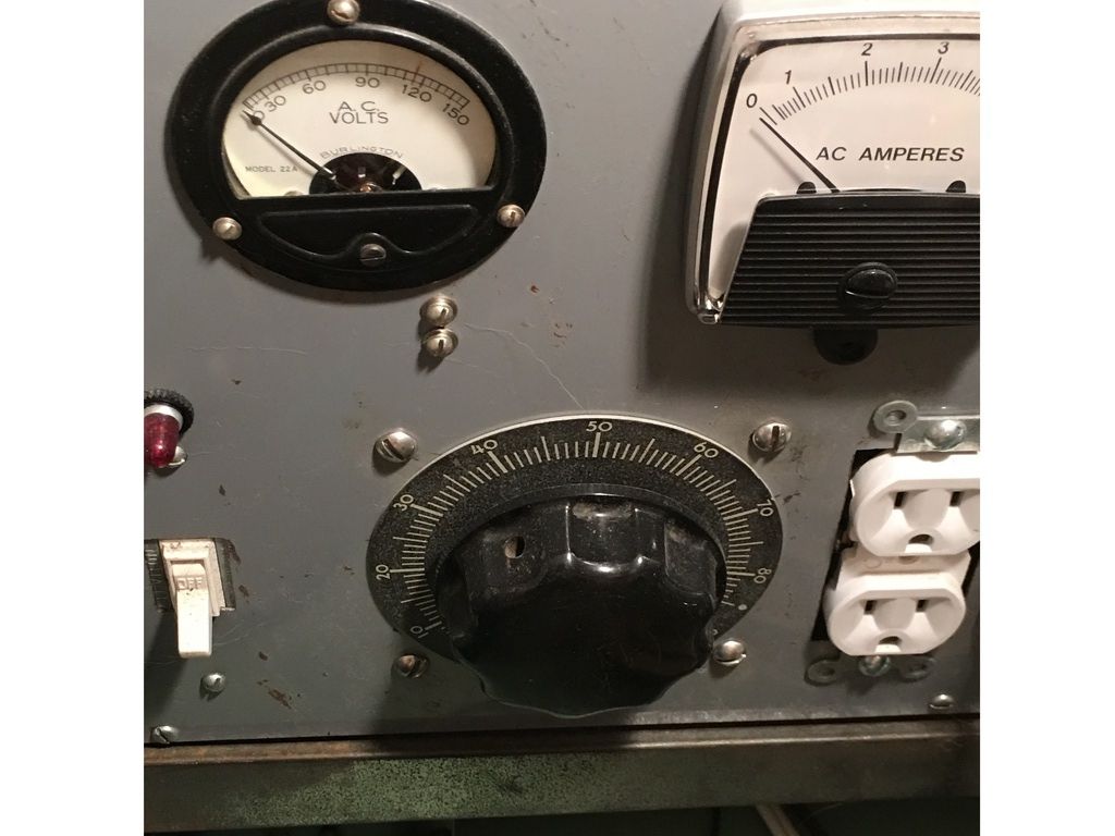
              I have a variac chassis I built a while back for the very purpose Dan mentions. Would you like to borrow it? Here's a picture (using it is pretty self explanatory):


              If you would like to use it, please email me through the board.

              Good luck and may the force be with you!!!

              Joe

              Comment

              • Richard M.
                Super Moderator
                • August 31, 1988
                • 11323

                #22
                Re: K66 Transistor Ignition - Delco Circuit Module Failure, Diagnosis and Repair

                Gents, Thanks very much for your ideas and offers. Joe, thanks, I may follow up to borrow it some time, thanks.

                However, here is the status of the Tek Scope.....It will be retired to be looked at another time when I have no other tasks. The reason?

                Last week, I was offered to accept, for only a marginal shipping fee, a practically BRAND NEW digital portable 2 channel oscilloscope!

                This is from a NCRS Member here on the TDB that graciously offered it to me as he has no use for it. It was shipped last week and I expect it here sometime this coming week. I will let him reply if he'd like, but for now I'll keep his generosity anonymous.

                I can't wait to get it and have some "Lab" fun with it.

                More to come.....

                Rich

                Comment

                • Joe R.
                  Extremely Frequent Poster
                  • May 31, 2006
                  • 1822

                  #23
                  Re: K66 Transistor Ignition - Delco Circuit Module Failure, Diagnosis and Repair

                  Originally posted by Richard Mozzetta (13499)
                  Gents, Thanks very much for your ideas and offers. Joe, thanks, I may follow up to borrow it some time, thanks.

                  However, here is the status of the Tek Scope.....It will be retired to be looked at another time when I have no other tasks. The reason?

                  Last week, I was offered to accept, for only a marginal shipping fee, a practically BRAND NEW digital portable 2 channel oscilloscope!

                  This is from a NCRS Member here on the TDB that graciously offered it to me as he has no use for it. It was shipped last week and I expect it here sometime this coming week. I will let him reply if he'd like, but for now I'll keep his generosity anonymous.

                  I can't wait to get it and have some "Lab" fun with it.

                  More to come.....

                  Rich
                  Rich,

                  That is very cool! Talk about paying it forward!!! I look forward to some screen shots from your new toy, er scope!!!

                  Joe

                  Comment

                  • Richard M.
                    Super Moderator
                    • August 31, 1988
                    • 11323

                    #24
                    Re: K66 Transistor Ignition - Delco Circuit Module Failure, Diagnosis and Repair

                    Originally posted by Joe Raine (45823)
                    Rich,

                    That is very cool! Talk about paying it forward!!! I look forward to some screen shots from your new toy, er scope!!!

                    Joe
                    Here you go....What's REALLY nice about this one, is you can store the images on a SD memory card. It has a built in slot for one. I had another old Delco board to play with. This time I ran a tach cable to the distributor and ran it from my Makita drill(Duke gave me the idea)


                    Here are a few waveforms.... I have to do more specific measurements checking the circuit timing so I can compare to the newer designs when I get some here. Top yellow trace is the Trigger transistor driving the Power transistors, bottom blue trace is the Coil+. I need to check specs but I believe the power output transistors are switching transistors, and pulse low for a specific time. I can't find specs using the Delco numbers....obsolete data.


                    Rich
                    Attached Files

                    Comment

                    • Patrick B.
                      Extremely Frequent Poster
                      • August 31, 1985
                      • 1995

                      #25
                      Re: K66 Transistor Ignition - Delco Circuit Module Failure, Diagnosis and Repair

                      Richard--- Years ago before new circuit boards were available for TI amps, I tried to find silicon transistors to replace the germanium transistors that were no longer available from Delco. I found that I could replace both of the power transistors (T-1 and T-2) with a silicon transistor MJ11015 and the units would work fine (but run a little hotter). I never found a good replacement for the T-3 transistor (GM part 1960643), probably because it needs fairly long legs and also the right size body diameter to fit in the cavity in the housing. I sold a few restored units and I have never heard any complaints in 30 years so I guess they are still working.

                      Comment

                      • Richard M.
                        Super Moderator
                        • August 31, 1988
                        • 11323

                        #26
                        Re: K66 Transistor Ignition - Delco Circuit Module Failure, Diagnosis and Repair

                        Patrick, Thanks for the info. I just looked up the Darlington number and they're still available.

                        Which package type did you use? Did you have to do much to modify the PCB?

                        Just curious. I'm not thinking about upgrading.

                        Rich

                        Comment

                        • Patrick B.
                          Extremely Frequent Poster
                          • August 31, 1985
                          • 1995

                          #27
                          Re: K66 Transistor Ignition - Delco Circuit Module Failure, Diagnosis and Repair

                          Richard -- They were in an identical package as the original transistors. They attached with the same screws. with no modification at all. That's why I was looking for a silicon equivalent to the T3 transistor that would be the same diameter with the same length legs. I think I found a similar one but the legs were shorter and the body diameter may have been too loose in the housing. Delco sold the 1960643 original T3's for $7.50 in the 80's so there may be some NOS still around. Many of the cores I collected had one of the T3's legs corroded off and could be repaired with a new T3. Your's looks exceptionally clean.

                          Comment

                          • Thomas B.
                            Frequent User
                            • July 31, 1984
                            • 38

                            #28
                            Re: K66 Transistor Ignition - Delco Circuit Module Failure, Diagnosis and Repair

                            Rich - Nice scope! Beats my Tek 422 ;-) Thanks for the updated images.

                            It still looks to me - assuming the timebase of the scope is calibrated and my math is not bad - that the trigger transistor is staying "high" too long. It has to go "low" before it gets "high" again. This means that maximum RPM is limited. Be nice to see a schematic to pinpoint possible bad components.

                            My logic - in the third image - first scope close-up the upper trace, as you say the trigger transistor, Frequency Readout says 90.4494Hz. This would correspond to a engine RPM of 1356.7. {1/90.4494Hz = period of 11ms} {11ms x 8 cyl = 88ms per distributor rotation} {88ms per rotation = 1/88ms or 11.3 RPs x 60 sec = 678.3 distributer RPM x 2 = 1356 engine RPM}

                            So I am really wondering what happens if you spin it faster. Looking at the scope traces, the amount of time that the Trigger Transistor stays "high" seems to be constant as the distributor rotational speed increases (from the video you posted on youtube, and confirmed by the second set of pictures although full pulse width only visible in first scope picture). It is "high" for 7ms, which corresponds to a maximum Engine RPM 2142.85 after that I think it is all over.

                            I have seen a TI module fail this way before, car would idle great but die when you revved it.
                            Tom Brady

                            Comment

                            • Richard M.
                              Super Moderator
                              • August 31, 1988
                              • 11323

                              #29
                              Re: K66 Transistor Ignition - Delco Circuit Module Failure, Diagnosis and Repair

                              Tom, Thanks for the detailed analysis. I started to take some more timing measurements yesterday but got distracted with other tasks but plan to do more when time permits. I've been thinking about using a pulse generator to drive the board instead of my borrowed TI distributor. I don't have one but am looking at that as a future option.

                              Yesterday I had a problem with the last original type module that I have here. The coil+ output terminal on the board broke off and I heard a noise and sure enough the 632 final stage output transistor failed. I removed it from the circuit and it was internally shorted. I had a spare 632 from a very old board and replaced it and it's now working again.

                              The original module that I also bench tested was sent out and reinstalled in the car. It runs fine, including high RPM, so my diagnosis long ago, suspecting it was bad due to a bad plug wire was erroneous. After my bench tests of it here, I decided to try it in the car again, sent it out, and it now works fine. However, I still want a modern upgraded module to replace it. I plan to do that soon.

                              There is a schematic of the module circuit in the 1967 CSM. There is also a detailed test procedure for testing the individual components. I'll scan that tomorrow and post it here.

                              Rich

                              Comment

                              • Richard M.
                                Super Moderator
                                • August 31, 1988
                                • 11323

                                #30
                                Re: K66 Transistor Ignition - Delco Circuit Module Failure, Diagnosis and Repair

                                A little late, but here's the Delco schematic with some notes. The TI Harness encases the resistors, depicted as R7 & R8, in the form of resistor wires. I verified these values with Dave Fiedler the other day as I don't have a TI harness here.


                                Also note the Power to both the Distributor Pickup Coil, as well as the Circuit module, is also connected to the Starter Solenoid "R" terminal. This supplies full battery voltage during crank to both destinations. I'm suspecting this may be a issue on some recent troubleshooting on the car. I think we have a intermittent solenoid contactor or wiring fault, providing unreliable "full" battery voltage at crank, causing problems with some TI boards and hot start issues with the Delco board.

                                Rich
                                Attached Files

                                Comment

                                Working...
                                Searching...Please wait.
                                An unexpected error was returned: 'Your submission could not be processed because you have logged in since the previous page was loaded.

                                Please push the back button and reload the previous window.'
                                An unexpected error was returned: 'Your submission could not be processed because the token has expired.

                                Please push the back button and reload the previous window.'
                                An internal error has occurred and the module cannot be displayed.
                                There are no results that meet this criteria.
                                Search Result for "|||"