Need help with connectors for signal-power-ground on the 4 small gauges for a 1964 - NCRS Discussion Boards

Need help with connectors for signal-power-ground on the 4 small gauges for a 1964

Collapse
X
 
  • Time
  • Show
Clear All
new posts
  • Claus S.
    Expired
    • December 30, 2010
    • 414

    Need help with connectors for signal-power-ground on the 4 small gauges for a 1964

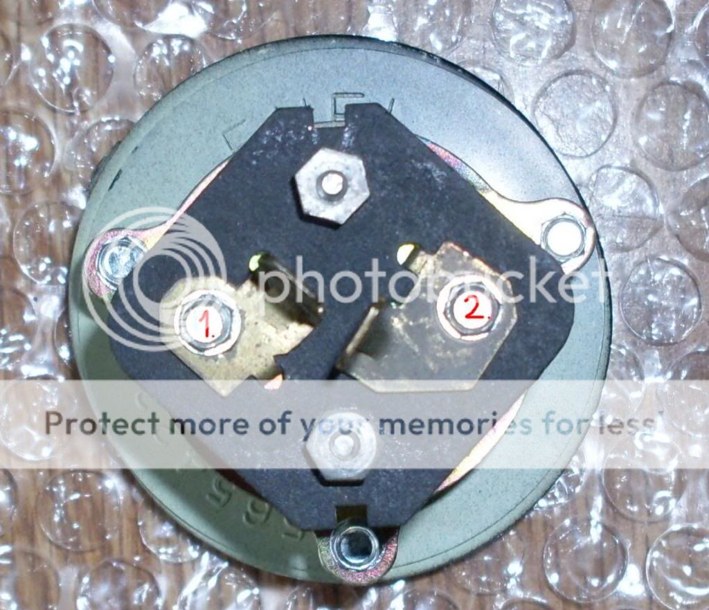
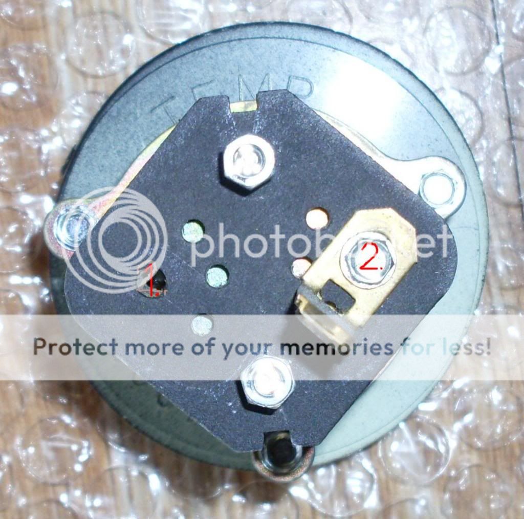
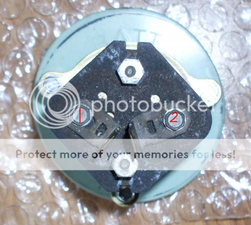
    I have marked the 2 connector tabs on each gauge with a number 1 and a number 2
    Does any know which connector on the gauges is for signal, power or ground?

    It does not help with the color of the wire but which connector on the gauges is for signal, power or ground


    Fuel gauge


    Temperature gauge(i am aware that one tab and screw is missing)


    Battery gauge
  • William C.
    NCRS Past President
    • May 31, 1975
    • 6037

    #2
    Re: Need help with connectors for signal-power-ground on the 4 small gauges for a 196

    I don't quite understand the question as neither is a power or ground in the typical definition. the temp circuit is powered via the 35 and 39e circuit where the 39 circuit supplies power . The 39 circuit would be the positive side, and pin 2. The battery gauge is actually a small voltmeter that measures voltage drop across a length of wire and infers a current flow from the resistance in the length of wire and the voltage drop. Wire circuits are 105 and 106, Black and red respectively NEITHER supplies power or ground by design. The fuel gauge again is not a direct power-ground situation, and the prientation of the terminals does not appearcorrectas the matng connector has the terminals in a "T" shape the top of the T is the 39D circuit, light green, and the 30 circuit is 18 ga Brown. That is about as good as I can decipher my 50 + year old wiring prints...
    Bill Clupper #618

    Comment

    • Claus S.
      Expired
      • December 30, 2010
      • 414

      #3
      Re: Need help with connectors for signal-power-ground on the 4 small gauges for a 196

      William. I mean which connector is for what. which wire from where on the car goes to connector 1 and 2 on each of the gauges


      Let me make a example. Temp gauge is like this connector 1 is for ? and connector 2 is the positive side(12 volt power?)

      Or like on the temperature gauge is connector 1 for the temperature sending unit and if so what is connector 2 for on the temperature gauge?
      Last edited by Claus S.; May 13, 2013, 07:12 AM.

      Comment

      • William C.
        NCRS Past President
        • May 31, 1975
        • 6037

        #4
        Re: Need help with connectors for signal-power-ground on the 4 small gauges for a 196

        Might help if I had a clue as to what you are trying to accomplish. Are you trying to build a wiring harness from scratch? The wiring diagram in the service manual should answer your question I think, but if you need more, I have the old wiring prints, however they are not in a reproducable format.
        Bill Clupper #618

        Comment

        • Claus S.
          Expired
          • December 30, 2010
          • 414

          #5
          Re: Need help with connectors for signal-power-ground on the 4 small gauges for a 196

          ILet me try to explain

          Here is a picture of the fuel gauge and the fuel sender. The connectors/tabs are marked with a number 1 and a number 2.

          Connector 1 is for the I terminal from the fuel sender
          Connector 2 is for the S terminal from the fuel sender

          I am not sure that this is correct so that is why i am asking

          It is this answers i am looking for about the gauges


          I did a search and found the temperature gauge

          Last edited by Claus S.; May 13, 2013, 10:35 AM.

          Comment

          • Alan D.
            Extremely Frequent Poster
            • January 1, 2005
            • 2038

            #6
            Re: Need help with connectors for signal-power-ground on the 4 small gauges for a 196

            Again you first need to answer William's question "what you are trying to accomplish"
            It would appear (guess) that all the connectors were removed from your gauges and you need to know what their orientation should be? YES??
            For example the connectors shown for your Temp Gauge are wrong. See picture
            One other word of caution do not use wiring diagram from the AIM, (was wrong)
            Attached Files

            Comment

            Working...
            Searching...Please wait.
            An unexpected error was returned: 'Your submission could not be processed because you have logged in since the previous page was loaded.

            Please push the back button and reload the previous window.'
            An unexpected error was returned: 'Your submission could not be processed because the token has expired.

            Please push the back button and reload the previous window.'
            An internal error has occurred and the module cannot be displayed.
            There are no results that meet this criteria.
            Search Result for "|||"