5690809 Flange & Cplg Assembly - bolt orientation - NCRS Discussion Boards

5690809 Flange & Cplg Assembly - bolt orientation

Collapse
X
 
  • Time
  • Show
Clear All
new posts
  • Jim S.
    Expired
    • August 31, 2001
    • 730

    5690809 Flange & Cplg Assembly - bolt orientation

    Jim Reinarts (36423) asked me if I had supporting information as to the direction and orientation of the shoulder bolts, lockwashers, and nuts that are used to assemble the 1963-1966 Corvette 5690809 Flange and Coupling Assembly (shown on my information drawing.)

    This was my answer to him.

    JR,
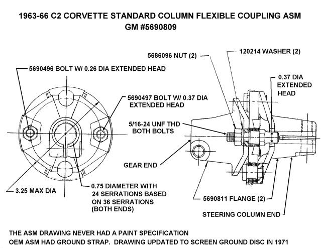
    The following information is all that I can currently supply as to the orientation and location of the shoulder bolts and attaching nuts and lockwashers that are used to assemble the 5690809 flange and coupling assembly (cplg asm).

    This cplg asm for the 63-66 (non-adjustable) standard Corvette steering column has the same flanges (5690811) on both the gear and steering column sides. So at that time 1963-1966 the steering gear input shaft and the standard Chevrolet steering column shaft were the same dimensions. So we can't draw any conclusions from those flanges as to direction of assembly.

    Typically a Saginaw cplg asm had shoulder bolts oriented such that the nuts and lock washers assembled from the steering column side. This was because the cplg asm was normally assembled to the gear at Saginaw and the car assembly plant had easier access to assemble and torque the nuts and lock washers if they were located on the steering column side of the assembly.

    However, way back in the middle 60's, if Saginaw assembled the 5690809 cplg asm to the gear and shipped it as a complete assembly to the Corvette assembly plant, the assembly plant wouldn't care about the location of the nuts and lockwashers since they were only installing and torquing the pinch bolt that attached the cplg asm to the steering column shaft.

    One last observation, the Saginaw Product Engineering drawings typically had the gear attaching end pointing to the left. Was this a hard and fast rule? Was it hard and fast back in 1962-63 when the drawing was made? Unfortunately, none of the draftsmen and engineers that would have actually made the drawing(s) nearly 50 years ago (and might know the answer) are deceased.

    Applying the above rule, the nuts would be on the gear side of the 5690809 cplg asm drawing.

    I probably should not have labeled my information drawing for the 5690809 cplg asm with the "gear end" and "steering column end" called out. I cannot find any Saginaw drawing information that supports the orientation of the shoulder bolts and the location for the nuts and lockwashers. If further supporting information is available, maybe I can leave the drawing alone.

    Jim Shea
  • Michael H.
    Expired
    • January 29, 2008
    • 7477

    #2
    Re: 5690809 Flange & Cplg Assembly - bolt orientation

    Originally posted by Jim Shea (36737)
    Applying the above rule, the nuts would be on the gear side of the 5690809 cplg asm drawing.


    Jim Shea
    I agree. I also have several assembly line pictures of new 63-66 chassis going down the line that show the nuts/washers on the forward/steering gear side. Hopefully, the link below will take you to a pic of a new 66 chassis/steering gear on the line.

    https://www.forums.ncrs.org/attachme...86248&uid=4137

    Comment

    • Jim S.
      Expired
      • August 31, 2001
      • 730

      #3
      Re: 5690809 Flange & Cplg Assembly - bolt orientation

      I take it that the picture shows the steering gear and cplg asm on the chassis before body drop and the steering column being inserted through the dash and connected to the cplg asm?

      Jim

      Comment

      • Michael H.
        Expired
        • January 29, 2008
        • 7477

        #4
        Re: 5690809 Flange & Cplg Assembly - bolt orientation

        Originally posted by Jim Shea (36737)
        I take it that the picture shows the steering gear and cplg asm on the chassis before body drop and the steering column being inserted through the dash and connected to the cplg asm?

        Jim
        Jim,

        Yes, that's correct. At this point, the engine was just being installed in the chassis.

        Also note, the entire top of the steering gear is coated with chassis black, as is at least one side of the coupler.

        Comment

        • Jim R.
          Very Frequent User
          • June 30, 2001
          • 643

          #5
          Re: 5690809 Flange & Cplg Assembly - bolt orientation

          Originally posted by Michael Hanson (4067)
          I agree. I also have several assembly line pictures of new 63-66 chassis going down the line that show the nuts/washers on the forward/steering gear side. Hopefully, the link below will take you to a pic of a new 66 chassis/steering gear on the line.

          https://www.forums.ncrs.org/attachme...86248&uid=4137
          Michael, thanks for this info and photo. JR
          JR

          Comment

          • Jim S.
            Expired
            • August 31, 2001
            • 730

            #6
            Re: 5690809 Flange & Cplg Assembly - bolt orientation

            Joe Lucia related that there was a different part number for the 1965-66 steering gear that was used with telescoping steering columns. That should indicate that the gear assembly was shipped from Saginaw with the correct flange and coupling assembly already attached. (Either 5677641 - with standard strg column; or 5694401 - with tele strg column).

            I don't know if security at Saginaw (now Nexteer and owned by the Chinese) will prevent me from reviewing the nearly 50 year old gear assembly drawing(s) or not. If the flange and coupling is shown on the 5677641 gear assembly drawing, that should answer once and for all what was the orientation of the shoulder bolts and whether the the nuts and lockwashers were on the gear side of the flange or on the steering column side.

            Jim

            Comment

            • Michael H.
              Expired
              • January 29, 2008
              • 7477

              #7
              Re: 5690809 Flange & Cplg Assembly - bolt orientation

              Originally posted by Jim Shea (36737)
              Joe Lucia related that there was a different part number for the 1965-66 steering gear that was used with telescoping steering columns. That should indicate that the gear assembly was shipped from Saginaw with the correct flange and coupling assembly already attached. (Either 5677641 - with standard strg column; or 5694401 - with tele strg column).

              I don't know if security at Saginaw (now Nexteer and owned by the Chinese) will prevent me from reviewing the nearly 50 year old gear assembly drawing(s) or not. If the flange and coupling is shown on the 5677641 gear assembly drawing, that should answer once and for all what was the orientation of the shoulder bolts and whether the the nuts and lockwashers were on the gear side of the flange or on the steering column side.

              Jim
              Jim,

              That's correct. The two different steering gear assy's that were used at the St Louis assy plant for 63-66 each had a unique part number. One for 63-66 with standard steering column and another for 65-66 with telly column. The difference was the coupler.
              Both gear assy's arrived at the St Louis plant with the coupler installed.
              Both part numbers were assembly line only and never available in service.

              For service, there was a third part number that would service all 63-66. (and probably also 67) This would be the steering gear only and did not include the coupler.

              I can look up the part number for the service steering gear without coupler, if necessary.

              Comment

              • Jim S.
                Expired
                • August 31, 2001
                • 730

                #8
                Re: 5690809 Flange & Cplg Assembly - bolt orientation

                The service gear (without the flange and coupling asm) was 5677642. I got the number from Joe a couple days ago. That would be the gear with full round input shaft serrations (no flat) and a "whistle" notch for the pinch bolt to pass through. That gear asm probably had a cast iron top cover. I don't believe the gear part number changed when the cover material was changed from cast iron to an aluminum die casting.

                Jim

                Comment

                • Michael H.
                  Expired
                  • January 29, 2008
                  • 7477

                  #9
                  Re: 5690809 Flange & Cplg Assembly - bolt orientation

                  Originally posted by Jim Shea (36737)
                  The service gear (without the flange and coupling asm) was 5677642. I got the number from Joe a couple days ago. That would be the gear with full round input shaft serrations (no flat) and a "whistle" notch for the pinch bolt to pass through. That gear asm probably had a cast iron top cover. I don't believe the gear part number changed when the cover material was changed from cast iron to an aluminum die casting.

                  Jim
                  I don't remember when the aluminum cover first appeared. Just a guess... 1969 or 70?
                  That may have been around the same time the input shaft changed also?

                  My parts book coverage is a bit limited for 68 and newer.

                  Comment

                  • Jim S.
                    Expired
                    • August 31, 2001
                    • 730

                    #10
                    Re: 5690809 Flange & Cplg Assembly - bolt orientation

                    I have in my notes that both the flat on the input (worm) shaft and the change from cast iron to die cast aluminum top (side) cover were both late 1969 running changes.

                    I can refer to two gear assembly drawings:

                    7806900 was released for production on 5-29-68. This gear drawing shows a full round serration on the input shaft and a 7802483 aluminum die cast top (side) cover.

                    Also

                    7812913 was released for production on 9-1-70. This gear drawing shows a flatted input shaft and the 7802483 aluminum top cover.

                    I do not have any drawing information before the 7806900 gear asm.
                    There could be an interim gear assembly (whose part number would be somewhere between 780900 and 7812913. But remember the die cast top cover is already shown on the older ...0900 drawing.
                    The flat shows up only on the later ...2913 drawing.


                    This is important, the Released for Production date on the drawings have little if any relationship as to when the change(s) actually went into production. Normally you would expect that the engineering released for production date could be 6 months to a year before actual startup. However, drawing prioreties, emergency changes, long lead equipment, and many other factors could have a great affect upon the drawing release date and actual production.

                    You should expect that normally the Released for Production drawing date would have to preceed the actual production date; since all planning, tooling, and manufacturing work should be initiated by the Released for Production authorization and the distribution of checked drawings.

                    Jim

                    Comment

                    • Jim R.
                      Very Frequent User
                      • June 30, 2001
                      • 643

                      #11
                      Re: 5690809 Flange & Cplg Assembly - bolt orientation

                      63 shop manual shows the nuts to the gear box side in one photo under standard steering.
                      JR

                      Comment

                      • Joe L.
                        Beyond Control Poster
                        • February 1, 1988
                        • 43219

                        #12
                        Re: 5690809 Flange & Cplg Assembly - bolt orientation

                        Originally posted by Jim Shea (36737)
                        I have in my notes that both the flat on the input (worm) shaft and the change from cast iron to die cast aluminum top (side) cover were both late 1969 running changes.

                        I can refer to two gear assembly drawings:

                        7806900 was released for production on 5-29-68. This gear drawing shows a full round serration on the input shaft and a 7802483 aluminum die cast top (side) cover.

                        Also

                        7812913 was released for production on 9-1-70. This gear drawing shows a flatted input shaft and the 7802483 aluminum top cover.

                        I do not have any drawing information before the 7806900 gear asm.
                        There could be an interim gear assembly (whose part number would be somewhere between 780900 and 7812913. But remember the die cast top cover is already shown on the older ...0900 drawing.
                        The flat shows up only on the later ...2913 drawing.


                        This is important, the Released for Production date on the drawings have little if any relationship as to when the change(s) actually went into production. Normally you would expect that the engineering released for production date could be 6 months to a year before actual startup. However, drawing prioreties, emergency changes, long lead equipment, and many other factors could have a great affect upon the drawing release date and actual production.

                        You should expect that normally the Released for Production drawing date would have to preceed the actual production date; since all planning, tooling, and manufacturing work should be initiated by the Released for Production authorization and the distribution of checked drawings.

                        Jim

                        Jim------


                        I think there were several steering gear changes for 1969. I think the cast aluminum cover was used for most, if not all, of the 1969 model year. I have a friend who is the original owner of his 1969 and his car was built in October, 1968. His car has the aluminum cover. If any cast iron covers were used, it must have been limited to VERY early 1969's.

                        My original owner 1969 also has the aluminum cover. In addition, it has the "full round" input shaft configuration like 1963-E69. My car was built in September, 1969.

                        Sometime after my car was built, I believe the steering gear changed again to the "with flat" input shaft. I don't know just when that occurred but it must have been sometime during the mid-September, 1969 to late December 1969 period.
                        In Appreciation of John Hinckley

                        Comment

                        • Michael H.
                          Expired
                          • January 29, 2008
                          • 7477

                          #13
                          Re: 5690809 Flange & Cplg Assembly - bolt orientation

                          Originally posted by Jim Reinarts (36423)
                          63 shop manual shows the nuts to the gear box side in one photo under standard steering.
                          Thanks Jim. I forgot about the one in the 63 service manual.
                          Last edited by Michael H.; August 12, 2011, 12:12 AM.

                          Comment

                          • Jim S.
                            Expired
                            • August 31, 2001
                            • 730

                            #14
                            Re: 5690809 Flange & Cplg Assembly - bolt orientation

                            Thanks Joe.

                            BTW, it appears that we have some pretty convincing proof that the attaching bolts, nuts, and lockwashers were pointed toward the steering gear. I am still trying to review the actual Saginaw product drawing. I may have some information next week.
                            Jim

                            Comment

                            • Jim S.
                              Expired
                              • August 31, 2001
                              • 730

                              #15
                              Re: 5690809 Flange & Cplg Assembly - bolt orientation

                              Here is a portion of the actual 1963-66 steering gear assembly drawing. Note that the flange and coupling assembly was shipped from Saginaw attached to the gear. The orientation of the flange and coupling assembly was such that the attaching nuts were pointing toward the steering gear.


                              Also there was a note on the drawing indicating that the gear should be painted "all over" with black paint except the pitman shaft. I assume that the note meant that the flange and coupling asm would have been attached and painted as well.

                              The attaching pinch bolts to the steering gear input shaft and to the flange on the steering column were both listed as 5686553. The bolt used to attach the flange and coupling asm to the steering gear input shaft was supplied and assembled at Saginaw. The bolt used to attach to the flange and coupling assembly to the steering column was supplied by Chevrolet and assembled at St. Louis (the bolt outline is dotted in the side view of the gear.)

                              NOTE: Section D-D there is a indentation on the end of the gear input shaft. It is vertical when the gear is exactly on center. The flange and coupling assembly assembles to the input shaft with the pinch bolt saw slot in line with the indentation.
                              Jim
                              Last edited by Jim S.; June 30, 2011, 08:57 PM.

                              Comment

                              Working...
                              Searching...Please wait.
                              An unexpected error was returned: 'Your submission could not be processed because you have logged in since the previous page was loaded.

                              Please push the back button and reload the previous window.'
                              An unexpected error was returned: 'Your submission could not be processed because the token has expired.

                              Please push the back button and reload the previous window.'
                              An internal error has occurred and the module cannot be displayed.
                              There are no results that meet this criteria.
                              Search Result for "|||"