Manometer Scale Interpretation help - NCRS Discussion Boards

Manometer Scale Interpretation help

Collapse
X
 
  • Time
  • Show
Clear All
new posts
  • Joe G.
    Expired
    • January 31, 2002
    • 89

    Manometer Scale Interpretation help

    Hello all,

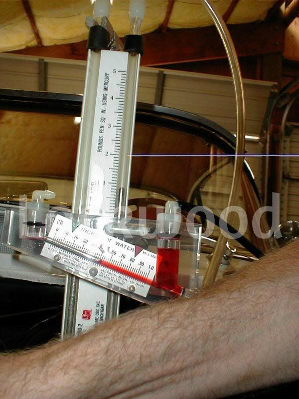
    First time using a manometer. My manual says to set 1" HG displacement at .5" water vacuum to set the econ stop. Is that 1.0" HG read directly off of the scale or is it split .5 on the down side and .5 on the up side to equal 1"? I have some conflicting info in my tuning literature.

    The Kent-Moore manual says "total displacement of manometer must be read therein from low point on one side of tube to high point on opposite side of tube." The 63 shop manual makes no mention of this.

    Thanks for setting me straight. It is a Kent Moore J7090 unit.
    Joe
  • Joel F.
    Expired
    • April 30, 2004
    • 659

    #2
    Re: Manometer Scale Interpretation help

    I think it is 1", but do not know for sure. I would give Jerry Bramlett a call. You will have an answer in 5 minutes.

    Comment

    • Dan H.
      Extremely Frequent Poster
      • July 31, 1977
      • 1365

      #3
      Re: Manometer Scale Interpretation help

      Hi Joe, assume you have a 'T' fitting for your main diaphram connection? Set the slide to zero on the mercury tube at bottom of the miniscus curve. You will read it on the scale side only, the fuel pressure will be forcing the other side down and raising the scale side. Suggest about .9 HG, not 1HG. Also do it carefully several times, takes time for the pressure to fully develope in the mercury tube. Follow steps to 'zero' the red water tube with vents open. Set fast idle cam to adjust the water manometer to .5, then observe the mercury and adjust the lean stop to achive the .9 of mercury. Suggest you go to Jerry Bramletts web sight for helpful hints and tools to help set you FI.
      Dan
      1964 Red FI Coupe, DUNTOV '09
      Drove the 64 over 5000 miles to three Regionals and the San Jose National, one dust storm and 40 lbs of bugs!

      Comment

      • Joe G.
        Expired
        • January 31, 2002
        • 89

        #4
        Re: Manometer Scale Interpretation help

        Thanks guys. Here is the way I am plumbed with the "T" and using the #8 nozzle with the service loop (vac adv line removed for clarity). Thanks for the tip on the .9" HG and letting the mercury stabilize on it's reading. Jerry's info on his website is great. I thought this might have sounded like a dumb question to ask but I just wanted to make sure I was interpreting what I was measuring correctly vs the statement in the manual. Back to tuning...
        Attached Files

        Comment

        • Dan H.
          Extremely Frequent Poster
          • July 31, 1977
          • 1365

          #5
          Re: Manometer Scale Interpretation help

          Hi Joe, looks good! Question, what is holding the plastic tubing in the 'T' fitting. I have a short pipe sticking out to slip the hose onto.
          Dan
          1964 Red FI Coupe, DUNTOV '09
          Drove the 64 over 5000 miles to three Regionals and the San Jose National, one dust storm and 40 lbs of bugs!

          Comment

          • Joe G.
            Expired
            • January 31, 2002
            • 89

            #6
            Re: Manometer Scale Interpretation help

            Hi Dan,
            You have a good eye. It is a compression sleeve that came with the T fitting. Just happened to be the right size to go over the tube and snug up. It works but your pipe idea is better.

            Joe

            Comment

            • Jim L.
              Extremely Frequent Poster
              • September 30, 1979
              • 1804

              #7
              Re: Manometer Scale Interpretation help

              Joe,

              Several comments about using a manometer to calibrate a 7375 unit. Refer to the photo below:


              I have a special "T" fitting that temporarily replaces the normal fitting on the main diaphragm cover. The nipple on this fitting is the point to which I connect the water manometer. This keeps the cranking signal valve fully operational.

              Note in the photo that I've temporarily re-located the cranking signal valve. This is so I can mount a (normally closed) needle valve on the enrichment diaphragm. Why, you ask? When it's time to calibrate the power stop, I crack open the needle valve just enough to allow the ratio lever to transition to the rear. This makes it easy to take a reading and return to a leaner mixture quickly.

              Finally, look closely at the #8 nozzle where the fuel tap is connected. I've found it very convenient to install a fuel shutoff valve there. This lets me bring the engine up to calibration speed without having to be concerned about the fuel trap filling prematurely.

              One note about the mercury manometer.... it reads in units of PSI, not inches of mercury. In fact the scale dimensions are NOT inches; just lay a ruler along side and this becomes apparent. Too, on the white background, for the mercury manometer, it even says PSI:


              Finally.... how do you have your manometer mounted? It appears that you are clamping the mercury U-tube directly. Does your manometer not have a mounting bracket?


              Good luck with your calibration.

              Jim

              Comment

              • Joe G.
                Expired
                • January 31, 2002
                • 89

                #8
                Re: Manometer Scale Interpretation help

                Great tips and tricks Jim. I see that you have taken alot of the stuff that is a little ackward about this process and made it more user friendly. Thanks for sharing your insight. No I don't have a mounting bracket. Sounds like I am supposed to. I am clamped lightly with the alternator bolt, just enough to hold it upright and level. I used a hemostat on the fuel line to keep it cut off. Fuel shut off valve would be much better.
                What kind of rpm sounds right to get .5" water vac? The manual says 1800-2200 but doesn't specify year or unit. I have heard higher for '65 380 units.

                Joe

                Comment

                • Jim L.
                  Extremely Frequent Poster
                  • September 30, 1979
                  • 1804

                  #9
                  Re: Manometer Scale Interpretation help

                  Originally posted by Joe Greer (37305)
                  Great tips and tricks Jim. I see that you have taken alot of the stuff that is a little ackward about this process and made it more user friendly.
                  As conceived and delivered, the manometer is not, in my opinion, completely thought out. I just added some things that I found would make using the manometer more convenient (or maybe "less inconvenient" would be more accurate).

                  What kind of rpm sounds right to get .5" water vac? The manual says 1800-2200 but doesn't specify year or unit. I have heard higher for '65 380 units.
                  1800 - 2200 is about what I see. I calibrated one 7375 unit a couple of years ago that required 3000 RPM to make the .5" water signal. Most solid-axle FI units need around 2300 - 2500, in my experience.

                  One other tip: Calibrate the two stops with the Idle Fuel screw turned all the way in. It takes three hands to do this but, in my opinion, you get better results.

                  Here's why: Turns out that at the throttle position that results in the .5" water signal, there is still appreciable signal boost from the idle/low speed vacuum circuit. This residual vacuum interferes with an accurate water manometer reading. Closing the Idle Fuel screw forces the water signal to be 100% from the venturi.

                  The procedure is like this:

                  1. Bring engine speed up to ~2000 and hold it with the fast idle cam
                  2. Close Idle Fuel (note how many turns)
                  3. Open water manometer valve
                  4. Adjust engine speed for .5" water signal
                  5. Open fuel valve (if present) and take reading
                  6. Adjust stop screw (if you are inclined to do so with the engine running. I'm not.)
                  7. Re-open Idle Fuel to its prior setting.
                  8. Close fuel valve
                  9. Let engine return to idle.
                  10. Close water manometer valve

                  Edit: left out a couple of trailing end steps....

                  Jim
                  Last edited by Jim L.; September 30, 2010, 06:33 PM.

                  Comment

                  • Dan H.
                    Extremely Frequent Poster
                    • July 31, 1977
                    • 1365

                    #10
                    Re: Manometer Scale Interpretation help

                    Jim, good point on the idle/air valve, never thought it would matter. Fuel shut off also will be helpful. Think my 380 comes in around 2500 for .5, I'll note it next tme I fool with it. When are you going to invent nozzle check valves so we don't percolate all our fuel after shut down?
                    Dan
                    1964 Red FI Coupe, DUNTOV '09
                    Drove the 64 over 5000 miles to three Regionals and the San Jose National, one dust storm and 40 lbs of bugs!

                    Comment

                    • Joe G.
                      Expired
                      • January 31, 2002
                      • 89

                      #11
                      Re: Manometer Scale Interpretation help

                      Thanks Jim. So studying your photo I noticed your CSV was relocated to where my vacuum advance line tap is. You must not be running a vac can in the distributor? I don't have a CSV or the provision in the enrichment diaphragm case to add the valve you added but with a little added plumbing to the signal line from the plenum this could be achieved. I just printed out your instructions and will take try out the idle mixture screw trick.

                      Comment

                      • Jim L.
                        Extremely Frequent Poster
                        • September 30, 1979
                        • 1804

                        #12
                        Re: Manometer Scale Interpretation help

                        Originally posted by Dan Holstein (1440)
                        When are you going to invent nozzle check valves so we don't percolate all our fuel after shut down?
                        Dan

                        Workin' on it, Dan. Workin' on it.....

                        Plan "B": Move to Wasilla

                        Jim

                        Comment

                        • Jim L.
                          Extremely Frequent Poster
                          • September 30, 1979
                          • 1804

                          #13
                          Re: Manometer Scale Interpretation help

                          Originally posted by Joe Greer (37305)
                          Thanks Jim. So studying your photo I noticed your CSV was relocated to where my vacuum advance line tap is. You must not be running a vac can in the distributor? I don't have a CSV or the provision in the enrichment diaphragm case to add the valve

                          Oh, whoops! My goof. Your unit looked like a 7375, but it must really be a 7380.

                          For 7380s, I bite the bullet and just unscrew the vacuum line to the enrichment diaphragm when it's time to set the power stop.

                          Your observation about my distributor is correct.... no vacuum advance. No good reason for not having it; it just doesn't.

                          Jim

                          Comment

                          Working...
                          Searching...Please wait.
                          An unexpected error was returned: 'Your submission could not be processed because you have logged in since the previous page was loaded.

                          Please push the back button and reload the previous window.'
                          An unexpected error was returned: 'Your submission could not be processed because the token has expired.

                          Please push the back button and reload the previous window.'
                          An internal error has occurred and the module cannot be displayed.
                          There are no results that meet this criteria.
                          Search Result for "|||"