The Broaching Process - NCRS Discussion Boards

The Broaching Process

Collapse
X
 
  • Time
  • Show
Clear All
new posts
  • Joe C.
    Expired
    • August 31, 1999
    • 4598

    The Broaching Process

    Broaching is a process used for various machining jobs, surface planing being one of them. The following links should provide some insight into the broach tooling used in the machining operations at Flint Engine, which was much larger than the one shown in the link. The purpose of this post is to illustrate the tool and its nature, and not to depict the actual size or configuration of the actual machine used at Flint Engine. The surface broach tool itself was flat, rectangular in shape with serrations which cut deeper on its trailing edge than on its leading edge. It resembled a huge flat file, and its size was large enough to cover the entire surface of the work, such that the machining operation was completed in one pass. In order to surface the entire engine deck(s) and oil pan flange, the broach tool would have had to be at least 11"-12" wide and probably many feet long. Small examples of the type of broach used are illustrated in the first link as "flats" in the photos, along with other types of broaching tools:


    The third link provides an excellent explanation of the mechanics of the cutting operation. The tool was drawn across the work, and the cut was completed in a single pass. The teeth on the leading edge of the tool would make a rough cut, with the teeth cutting deeper and finer as they progressed toward the tool's trailing edge. The sharpness of the teeth on the tool would determine the depth/prominence of the tool marks left on the work. The sharper the tool, the less pronounced the marks.

    One can easily imagine the enormous force that the work and holding fixture were subjected to during this single pass process, and the effect that that force had in determining any movement of the work relative to the cutting tool. The process was designed to produce as many finished engine blocks as was possible within a short time. Tolerances were on the order of tens of thousandths of an inch, especially when the tooling was in need of sharpening/replacement.
    Last edited by Joe C.; August 13, 2010, 10:22 PM. Reason: Clarification/elaboration
  • Clem Z.
    Expired
    • January 1, 2006
    • 9427

    #2
    Re: The Broaching Process

    figure 2 in item 3 is to be used for cutting a keyway in a gear or pulley

    Comment

    • Joe L.
      Beyond Control Poster
      • February 1, 1988
      • 43211

      #3
      Re: The Broaching Process

      Originally posted by Joe Ciaravino (32899)
      The following links should provide some insight into the broach tooling used in the machining operations at Flint Engine. The type of broach used was a flat broach, and is illustrated here:


      The third link provides an excellent explanation of the mechanics of the cutting operation. The tool was drawn across the work, and the cut was completed in a single pass. The sharpness of the teeth on the tool would determine the depth/prominence of the tool marks left on the work. The sharper the tool, the less pronounced the marks.

      It should also be considered the tremendous force that the work and holding fixture were subjected to during this single pass process, and the effect that that force had in determining any movement of the work relative to the cutting tool. The process was designed to produce as many finished engine blocks as was possible within a short time. Tolerances were wide.
      Joe------


      My recollection of the broaching machine at Flint was that it was much larger than the machine in this photograph. I think it was basically of this design, but much larger. Somewhere, among the thousands of photographs I have around here, I have photographs that I took at Flint Engine as part of an NCRS tour at the 1992 National Convention. I think I have about 4 rolls of film I took there and if I had had more film with me that day, I would have taken more.
      In Appreciation of John Hinckley

      Comment

      • Michael W.
        Expired
        • April 1, 1997
        • 4290

        #4
        Re: The Broaching Process

        Excellent write up Joe. Helps take the mystery out of the broaching operation.

        Thanks.

        Comment

        • Clem Z.
          Expired
          • January 1, 2006
          • 9427

          #5
          Re: The Broaching Process

          i wonder how much money GM saves on machine tooling costs since they went to aluminum blocks and heads ??? the tooling has to last a lot longer maching aluminum than cast iron

          Comment

          • Joe C.
            Expired
            • August 31, 1999
            • 4598

            #6
            Re: The Broaching Process

            Originally posted by Joe Lucia (12484)
            Joe------


            My recollection of the broaching machine at Flint was that it was much larger than the machine in this photograph. I think it was basically of this design, but much larger. Somewhere, among the thousands of photographs I have around here, I have photographs that I took at Flint Engine as part of an NCRS tour at the 1992 National Convention. I think I have about 4 rolls of film I took there and if I had had more film with me that day, I would have taken more.
            I usually hear the word "locomotive" when size descriptors are used.

            Comment

            • Terry M.
              Beyond Control Poster
              • September 30, 1980
              • 15595

              #7
              Re: The Broaching Process

              The tooling was such that two cylinder cases were worked in one pass. The top of one case and the bottom of the other. The up[per case was rotated for its lower rail to be machined. All this was happening automatically.

              The operator told us that on occasion when the machinery would "get out of whack" it could tear the wall out of the cylinder case.

              The noise and smoke rising from the cylinder cases was as impressive as the size of the machine. As I remember the bed that held the tooling was about ten feet high and maybe twenty feet long -- and all that moved with each pass.
              Terry

              Comment

              • Joe L.
                Beyond Control Poster
                • February 1, 1988
                • 43211

                #8
                Re: The Broaching Process

                Originally posted by Terry McManmon (3966)
                The tooling was such that two cylinder cases were worked in one pass. The top of one case and the bottom of the other. The up[per case was rotated for its lower rail to be machined. All this was happening automatically.

                The operator told us that on occasion when the machinery would "get out of whack" it could tear the wall out of the cylinder case.

                The noise and smoke rising from the cylinder cases was as impressive as the size of the machine. As I remember the bed that held the tooling was about ten feet high and maybe twenty feet long -- and all that moved with each pass.

                Terry------


                Plus, as I recall, the broach looked just about as old as most of the other equipment in the plant, much of which dated back to 1955. So, this machinery definitely was not "high tech", even by 1992 standards.
                In Appreciation of John Hinckley

                Comment

                • Kevin G.
                  Extremely Frequent Poster
                  • February 1, 2005
                  • 1076

                  #9
                  Re: The Broaching Process

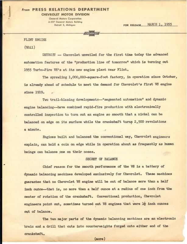
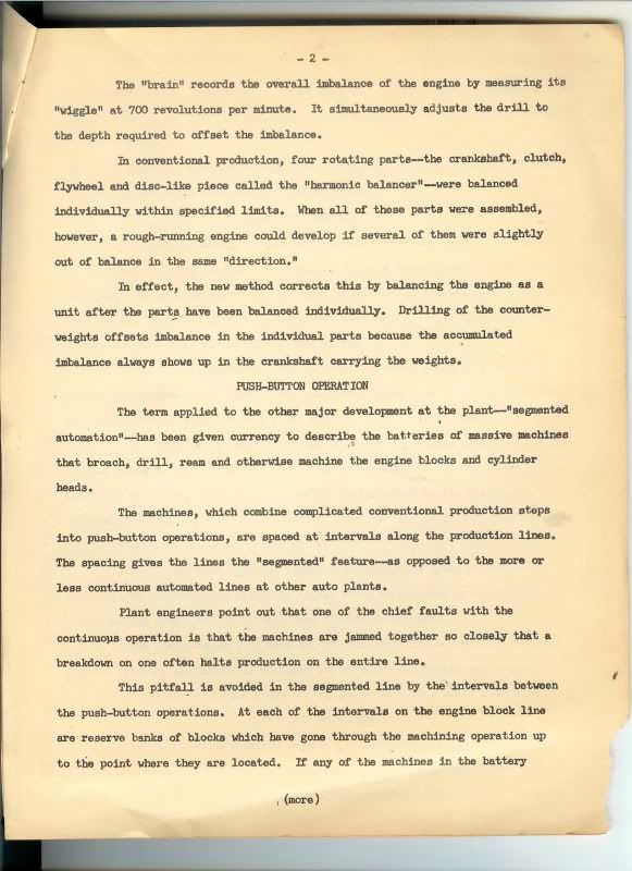
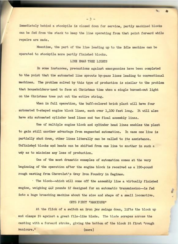
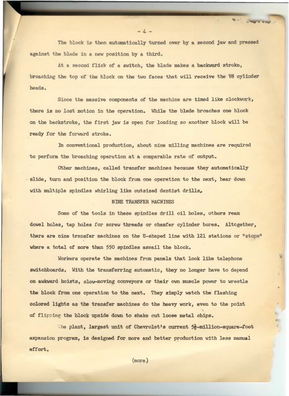
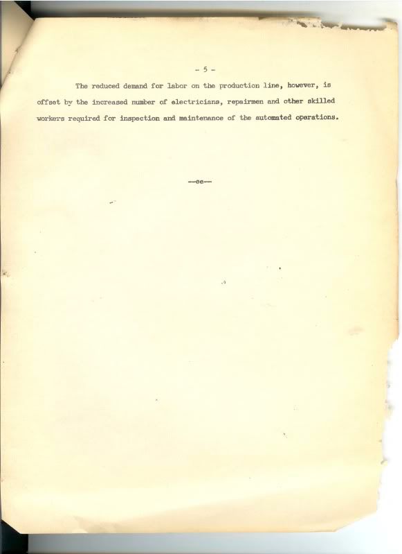
                  Perhaps many of you may have seen this Press Release in my small article published in the Restorer. It is an original, found in pile of old brochures.
                  Enjoy........


                  Comment

                  • Jack H.
                    Extremely Frequent Poster
                    • April 1, 1990
                    • 9906

                    #10
                    Re: The Broaching Process

                    Let's see...somewhere in my files I have a dark/fuzzy pix of the actual BEAST...
                    Attached Files

                    Comment

                    • Steven B.
                      Extremely Frequent Poster
                      • June 30, 1982
                      • 3985

                      #11
                      Re: The Broaching Process

                      How were the blocks mounted to the table?

                      Al. vs. steel tool life: Back in college when I ground truck beams (mounted tandem axles to the spring saddles). I ground both steel and aluminum. The steel tooling would last 3-4 times longer on the Al. and when using a belt grinder to clean up the ridges belts lasted 2-3 times. On piece work for beams I liked Al!

                      Side note: Another job I had while there (Hendrickson Tandem) was converting three IH Scouts to pull trees out of the forrests in Africa. Elephants were displaced. Two had CAT engines and the third had a Pontiac 326. I got to test drive them and much preferred the 326. .

                      Comment

                      • Jack H.
                        Extremely Frequent Poster
                        • April 1, 1990
                        • 9906

                        #12
                        Re: The Broaching Process

                        If memory serves, the blocks had 'registration' points on the outer sides that served to align them for the broaching process...

                        Comment

                        • John H.
                          Beyond Control Poster
                          • December 1, 1997
                          • 16513

                          #13
                          Re: The Broaching Process

                          Originally posted by Jack Humphrey (17100)
                          If memory serves, the blocks had 'registration' points on the outer sides that served to align them for the broaching process...
                          And the master x-y locators for the block on its machining pallet were two holes in the bottom surface of the pan rail - one adjacent to the fuel pump boss, and the other one in the middle of the starter mounting pad. See photos below.
                          Attached Files

                          Comment

                          Working...
                          Searching...Please wait.
                          An unexpected error was returned: 'Your submission could not be processed because you have logged in since the previous page was loaded.

                          Please push the back button and reload the previous window.'
                          An unexpected error was returned: 'Your submission could not be processed because the token has expired.

                          Please push the back button and reload the previous window.'
                          An internal error has occurred and the module cannot be displayed.
                          There are no results that meet this criteria.
                          Search Result for "|||"