Hello everyone,
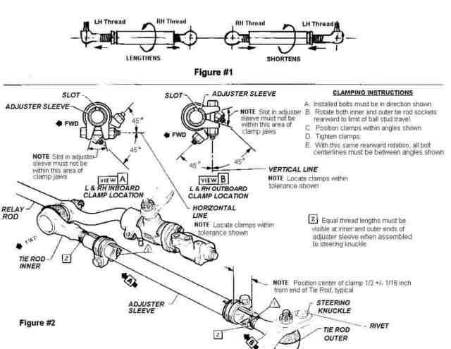
My tie rod tubes have a groove on one end. I am curious to the orientation/location of the grooved end on the tie rod tube, inboard or outboard? I know how my steering assembly came apart - the grooved end was outboard toward the steering knuckle. A search came up with some info from Joe Lucia as to the left/right threading and the yellow paint denoting right hand threads. This would put the groove on the tube on the left handed thread tie rod side.
What has me confused is whether or not my tie rod assemblies were removed at some point and put back in 180 degrees out. I wonder this because my tie rod ends with yellow inspection paint are on the inboard side (attach at relay rod) and not outboard like the TIM & JG notes. Both sides are identical. Or maybe it went down the line like this?
Any observations out there? Car is a 71.
Thanks,
Joe


Comment